Lab 1a: Be a Hardware Hacker!
CSE 141L, Spring 2007, Donghwan Jeon
Due 4/9 before the beginning of the class
Lab1a is a preparation stage for future labs, and consists of two parts - Xilinx ISE and Verilog. In Lab 1a, you will install Xilinx ISE and follow a step-by-step tutorial to learn essential concepts and working flow in hardware designs. For those who used Xilinx ISE in 140L, this lab would be very easy. Otherwise, you should START NOW - there might be many unexpected problems. If you have any question regarding this lab, please post it on the webboard.
Deliverables
- No lab interview for lab 1a. In future labs, you will have interview sessions with TA to show your results.
- Submit your report for questions below to TA.
Xilinx Quick Tutorial
Xilinx provides a good step-by-step tutorial. With this tutorial, you will be able to learn how to perform various activitisecan in the hardware design process. It should take less than two hours to follow the tutorial.
- Get Xilinx quick tutorial .
- Follow instructions in the tutorial. You will design a simple counter module in Verilog.
- Try to understand the Verilog source file used in the tutorial.
- Since we will use Verilog in this class, you should skip VHDL related sections.
- Also, you do not need to follow "Download Design to the Spartan-3 Demo Board". We will not be using a demo board for this assignment.
A Simple 8 bit Adder
Now that you know how to use XilinX ISE, we will examine a few aspects of hardware design. For more information, I highly recommend to skim through chapter 2 and chapter 5 of Xilinx In-depth Tutorial.
- Suppose that you got a job from 'San Diego Chip Factory'. Your boss gave you an adder design written in Verilog - adder.v to implement it in a Xilinx FPGA 'Virtex4 - XC4VLX15'. Your first assigned task is to understand the source file thoroughly, and make a project in Xilinx ISE.
- Q1. Draw a schematic for adder.v. In your schematic, you should clearly show the function of the design by using flip-flops, various gates, a comparator, an adder, and wires. Try to infer a schematic from the Verilog source, but it is fine to use a generated schematic from Xilinx ISE as long as it is detailed enough.
- To see what is really going on, perform a behavioral simulation. You need to make a proper Testbench Waveform file as you did in the Xilinx tutorial. Use timing parameters in the figure below - it is equivalent to 500MHz. Does it behave as you expected?

- You might have noticed that output 'isOdd' is updated one cycle later than 'out'. (Stupid...who wrote this?) Anyway, it is a good opportunity to show your performance. Modify the verilog file so that 'isOdd' is simultaneously updated with 'out'. Perform the same behavioral simulation you did in the previous step again. (Hint: what does 'a<=b' mean in Verilog?)
- Q2. Draw a schematic for your modified adder.
- After you checked your adder is functionally correct, it is time to synthesize. In the synthesize stage, Xilinx ISE translates your Verilog design to what its backend stage(implementation stage) can understand. To synthesize a design, just double-click "Synthesize-XST" in the "processes" window. Xilinx ISE generates reports for each major stage. You can read them in the 'Design Summary' tab as shown in the figure below. Skim through the generated synthesis report.
- Q3. How many flip flops are used for the design? How many LUTs does XC4VLX15 have, and how many LUTs does your design use? What is the 'estimated' achievable maximum frequency? (Ignore numbers in the figure below.)

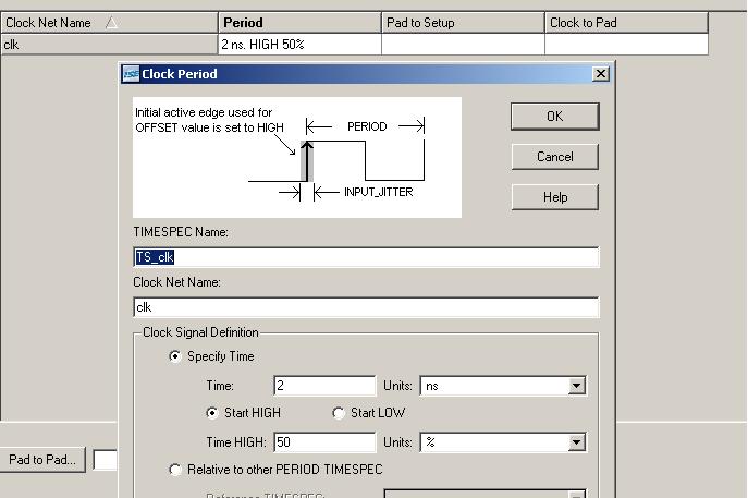
- To actually program your FPGA, you need to "implement" your design. "Implement" is the term the Xilinx tools use for the stage which decides how to configure LUTs and networks of FPGA. For implementation, first you need to specify your timing constraints. You are targeting 2ns cycle time and 50% duty cycle as in the figure below. (You do not need to set 'clock-to-pad' and 'pad to setup' constraints.) With these constraints, Xilinx will generate a clock signal which alternates between high and low every 1ns. Then double-click "Implement Design". After implementation, Xilinx will generate a few reports. Skim through them.
- You can see detailed timing information in 'static timing report'. In the report, you should see a term 'slack'. Slack is the time delay difference from what you expected(your timing constraints) to the actual delay. If slack is positive, it means your timing constraints are met and you might be able to increase frequency. Otherwise, you need to relieve your timing constraints so that no negative slack exists.
- Q4. How many 4-input LUTs and IOBs are used? As you learned in the Monday class, combinational logic is implemented by using LUT(Look Up Table) in FPGA. IOB(IO Block)s provide interfaces to external worlds. There are only limited number of LUTs and IOBs, so you should watch their usage carefully.
- Q5. Was your initial time constraint met? If not, what is the minimum achievable cycle time? Actually change timing constraints and implement your design again, making sure there is no negative slack in your implementation. In the figure below, the design has negative slack - which means it failed to meet timing constraints. What is the maximum operating frequency of your adder? Compare the frequency with 'estimated' minimum frequency you got in Q3. What caused the difference between two values? (Hint: See how much time is used for logic and delay respectively.)

- To show your boss that your adder would work at a certain frequency, you need to do a post-route simulation with the same testbench in Q2. Sometimes, post-route simulation is also used to verify the validity of your implementation. (The result of post-route simulation should tally with that of the behavioral simulation.) Running a post-route simulation is very similar to running a behavioral simulation. Select 'Post-route simulation' instead of 'Behavioral simulation' as shown in the following figure, then double-click 'Simulate Post-Place & Route Model'.
- Q6. Put two simulation results(behavioral and post-route) in your report. Are they the same each other? If not, why are they different? Modify test bench file, and make post-route simulation works correct. (Hint: Behavioral simulations do not have a sense of frequency while post-route simulations have.)

32 bit Adder
- Now that your adder works fine, your boss wants you to extend your adder to support 32bit additions. Modify your verilog source file, synthesize it, and implement it. (Hint: You can very easily extend the existing 8bit adder to 32bit.)
- Generally, the more complex and the bigger a design is, the slower it is. Two important causes are: (1) more complex logics usually use more LUTs, thereby increasing their logic delays, (2) as a design gets bigger, it is increasingly diffcult to place and route LUTs in their optimal places.
- Q7. Reported that bigger designs tend to be slower and use more resources, your boss is concerned in your adder's resource usage and the maximum operational frequency. To relieve his worries, fill out the following table. To impress him even more, include 16bit and 64bit adders, too.
| Width | Max Freq (synthesis report) | Max Freq (post P&R report) | # of used 4 input LUTs | # of used IOBs |
| 8 bit | | | | |
| 16 bit | | | | |
| 32 bit | | | | |
| 64 bit | | | | |
Multiplier
- Your next assigned task is to design a multiplier. You can easily make one by modifying your adder. First try a 32bit multiplier. For multipliers, the width of output should be (2 * the width of input), and they have to have 'isOdd' output.
- After synthesize, skim through the generated synthesis report. You should notice that DSP48s which you have not seen before are used for your design. Since multipliers are frequently used in digital designs, most Xilinx FPGAs include a few highly optimized multipliers such as DSP48.
- Q8. Fill out the following table for 32bit, 48bit, and 64bit multipliers. (8bit and 16bit multipliers had some problems in the implementation stage.) Note that some mulipliers might not fit in XC4VLX15 due to their demands on resources. In such cases, explain the reason.
| Width | Max Freq (synthesis report) | Max Freq (post P&R report) | # of used DSP48s | # of used IOBs |
| 32 bit | | | | |
| 48 bit | | | | |
| 64 bit | | | | |
- Q9. Draw two graphs for adders and multipliers with bit width as x axis and frequency(MHz) as y axis.
Free Form Experiment
- Q10. Now that you have gotten your feet wet with the tool, it's time for some free exploration. Design an experiment that answers some kind of question you have about the tool, and report on the results.
Useful Resources