CSE 140L Lab 3 - Finite State Machine Design
Spring 2007, Professor Cheng, TAs Thomas Weng, Chengmo Yang, Yi Zhu
Due time: Demonstrate by Friday 5/25 12:30pm, Report submitted online by Monday 5/28 11:59pm.
Important! Please regularily check http://webboard.ucsd.edu for the latest updates and news regarding this lab. FAQs and announcements will be on the webboard, so check it often!
Objective
- Learn how to use VHDL to design a finite state machine.
- Learn how to use schematic capture to design a finite state machine.
- Undesrtand that a FSM can be implemented with digital logic, and also with VHDL.
- Learn how to use the FPGA to demonstrate your FSMs through the outputs and through the monitor connection.
- Learn the difference between Mealy and Moore machines and compare their results with different state assignments.
Part 1. Mealy vs Moore FSM
In this part you are asked to build a simple traffic controller. The output is two traffic lights, one for north-south and one for east-west. The traffic lights should be implemented using the two LED outputs on your board as shown in the following figure.
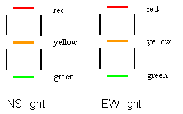
The two push buttons on your board should be used as the two input "Walk" signals, one for each direction. By default the NS direction is given a higher priority. This means the green light on the NS direction and the red light on the EW direction should be on. The FSM will keep in this default state unless WalkNS = off and WalkEW = on. This input combination will cause the FSM to advance to another state and the yellow light on NS to be on. The yellow light will hold for one clock cycle. Then the red light on NS and the green light on EW will be on at the same time. The green light on EW holds for two cycles no matter what the input signals are. After that, if the input signals are still "WalkNS = off and WalkEW = on", the state of the FSM will not change. Otherwise, the yellow light on EW will be on, and after one cycle the red light on EW and the green light on NS will be on at the same time. At that time, the traffic controller is back to the default state.
You need to implement this traffic controller using no more than 3 D flip-flops. Furthermore, you need to implement two solutions, one Moore (outputs only depend on the current state) FSM and one Mealy (outputs depend on both the current state and the inputs) FSMs. For this lab, we will provide you a directory with qpf and schematic file to help you get started. In order to make this lab work for your FPGA board, you will need to make use of the debouncing module, which is implemented in VHDL. We will give you the framework for this, including the flip flops, clock circuitry, and switches. We also will give you the VCC circuitry to blank out all the unneccessary segment outputs. You will fill in the rest.
Download Moore template
You will notice that we have given you some basic circuitry. You have two inputs, PB1 and PB2 (which passes through the debouncer). You also have access to the current states (going into the flip flops) and the next state (comming out of the flip flops). Using this, you will implement your circuit.
Report:
- Include the FSM of your traffic light controller
- Include the state/output table of your traffic light controller
- Include schematic diagrams of your circuit
- No need to include functional and timing! Yay!
-Assume at cycle 0 the FSM is in the default state and the inputs are "WalkNS = off and WalkEW = on". At cycle 3 the inputs become "WalkNS = off and WalkEW = off". At which cycle will the Moore FSM turn back to the default state? What about the Mealy FSM?
Part 2. The Train!
You will design the FSM for a train controller, and you will demonstrate your train on the monitor. We will provide the foundation of the code, including the VHDL file that connects to the monitor, as well as other files that you will need. All you need to do is edit the tcontrol.vhdl file to implement your control circuitry.
The basic description of your train is as follows: You have two trains going counter-clock wise on two seperate tracks, except for a shared track on the bottom. When train A occupies the the shared track, then B obviously cannot go, and vice versa.
Therefore, you will be designing the control system for the trains. You will have four inputs - sensors 1, 2, 3, and 4. Each of these sensors returns a 0 or a 1 depending on if the train just went past it. You will also have four outputs - SW1 and SW2, and DirA and DirB. SW1 and SW2 are the switch controls that determine which track the shared track is connected to. A value of 0 means that the shared track is connected to Track A (Train A's track) and a value of 1 means that the shared track is connected to Track B (Train B's track). In addition, DirA and DirB control whether or not the train goes or stops. A value of 00 causes the train to stop, and a value of 01 causes the train to go (note, there are TWO bits for DirA and DirB. The reason is because a value of 10 causes the train to reverse).
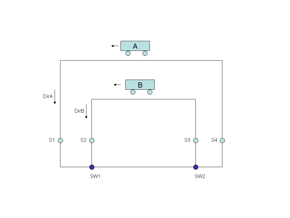
From these 4 inputs and 4 outputs, you are able to design the control system that will ensure that the two trains never collide. Thus, the way this works is that when both trains are choo-chooing on the outside of the tracks, all four sensors will be 0. One train will eventually hit their respective sensor however (sensor 1 for A, 2 for B). When this happens, this means that that train now is in the shared track. The switches need to be changed so that the switches are connected to that train's track. Eventually the other train will try to get in on the shared track. The sensor will see this and should stop the train from moving. When the first train goes past the 2nd sensor (S3 or S4), that means that the train is now past the shared track. The stopped train can now proceed. Train A has priority over Train B, so if both A and B were to hit S1 and S2 at the same time, A would get to go.
You will be designing this control system in a step-by-step manner. The first thing you will draw out is the Finite State Diagram (Moore). Next, you will draw out the output/state table. (Outputs are on the left side of the table, states are on the top). Then you will implement this in VHDL. We will give you the framework, so all you need to do is fill in the blanks. You will need to demonstrate this lab to us during OH.
The zip file is here: Train Files. Unzip it and you will see the vhdl files that we have given you. Follow these directions to get started. You will want to open up tcontrol.vhdl, as that is what you need to edit. Follow along with the comments we added in tcontrol so that you can see what you need to do.
There are two parts that you will modify: the state transitions part, and the output part. Once you are done with that, proceed to compile and program, like any other project. After that, connect your board to the monitor and verify that the output looks good. We have included a video file of what the output should look like here .
VHDL Tutorial - this tutorial is pretty good for VHDL. While you probably do not really need to go through it, some of you might be more interested. The edits you have to make will be pretty easy, assuming you guys have programming experience. There are many tutorials out there that you can search for. This class is not a VHDL design class, but at the least you should be able to look at a fairly simple VHDL file and have a good idea of what it is doing. For kicks, you can take a look at the VHDL for train.vhd. It controls the monitor outputs. You can see how much more complicated it is for the FPGA to display even simple images on the screen.
Coolness! You can control the speed of your train with the switches! Go try and see what happens! The first four switches control the speed of one train, and the next four control the other train!
Report:
- Include the FSM of your train controller
- Include the state/output table of your train controller
- Include the VHDL code of your train
- Write a 1/2 page description of what your VHDL code is doing for tcontrol. Start from the top and go towards the end. Convince us that you know what each major segment of the VHDL is doing. The major segments are the ENTITIY part, the ARCHITECTURE PART, the "PROCESS (clock) part", and the "WITH state SELECT" part. Relate the FSM with the VHDL code by explaining how the VHDL implements the FSM you came up with.
- Let's have some fun with our train! Let's pretend we are Amtrak and forget to change the switch outputs when we need to, i.e. switch 1 and 2 are set incorrectly so that the incomming trains will derail. Try it! Describe what happens!
- Rememeber that you can make the trains go backwards by setting DirA or DirB to 10! Reverse the B train. Make train B go clockwise instead of counter-clockwise. This will require some updates to the outputs and state transitions, as now our sensor 3 becomes the "incomming" sensor and sensor 2 becomes the "outgoing" sensor. (Hint, this won't require too many changes... ). Copy and paste the VHDL parts that you had to change to make this work.
BONUS POINTS: for 5 bonus points, demonstrate for us some wacky or interesting train pattern. Vary the speeds, mess with the outputs, states, etc. See what you can do! Close calls are always fun... things to try include reversing B onto A and seeing what happens, or doing head-on collisions, etc. You can get B onto A's track or vice versa, or you can do funny train patterns. Have fun and be creative!! Note, for this, the best advice I have is try weird things, a lot of times your trains will halt, or get stuck, so try some other combination or vary the speeds to get interesting situations. (The reason this happens is that your states might no longer make sense, such as the case when both A and B are on the same track, and one of the trains hits a sensor. You can fix this by adding the correct states, or you can try varying the speeds so that one train goes way faster than the other, ends up on the same track, and then rams the other train (before your train controller realizing something is wrong and freezing your trains). This one is for you guys to have fun and try fun things, so don't worry about making a system that actually is correct!).
Part 3. State Encoding
In this part you are asked to build a 4-bit up/down gray counter using 4 D flip-flops and combinational gates. The output is 4-bit Gray code D3D2D1D0. Your counter should have two input signals: counter enable (pb1) and counter direction (pb2).When pb1 = 0 (pushing the button), the counter will count in the direction specified by pb2, and it will stop counting when pb1 = 1 (leaving the button not pushed). The counter will counts up when pb2 = 1, and down when pb2 = 0 (pushing the button). The up and down sequences are shown as follows:
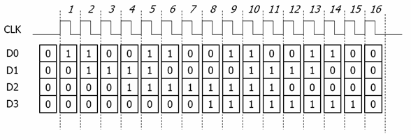
Up sequence: 0000, 0001, 0011, 0010, 0110, 0111, 0101,0100, 1100, 1101, 1111, 1110, 1010, 1011, 1001, 1000
Down sequence: 1000, 1001, 1011, 1010, 1110, 1111, 1101, 1100, 0100, 0101, 0111, 0110, 0010, 0011, 0001, 0000.
You will implement this gray counter in VHDL code with three different encoding schemes: sequential, one hot and gray codes. We will provide you a VHDL template.
Your job is to figure out the state transitions part and the state encoding part.
We have included a template VHDL file to help you get started. You will need to fill in
the component definition for the segment display. You also need to finish the
state transitions. This is very similar to what you had to do for part 2.
We have given
you two states to help you get started. Your job is to finish the VHDL file, and then
program your board. Run it on your board to see what happens. Also, you will change the
state encoding and try gray, one hot, and sequential encoding. Look at the number of gates
that each encoding scheme requires.
Download Gray Counter VHDL File
Directions and hints:
- Create a new project called GrayCounter. Download the VHDL file as the top module. You need the clock division module and segment display module to compile.
- The available encoding options are named as "sequential", "gray" and "one-hot".
- You can find the number of logic elements in the compilation report after you compile your project successfully.
- In your simulation diagrams, only show the input and 4-bit output (i.e. the code_out part).
Report:
- Include the VHDL code of your counter
- Describe in a short paragraph what happens when you run your grey counter on your
FPGA board.
- Why is this called a gray counter?
- You need to bypass the clock division module to perform the simulation. How do you modify the code?
- Compare the complexity of your three implementations. How many logic elements
does each implementation require?
How many number of flip-flops does each implementation require?
- Compare the performance of your three implementations. What is the minimal clock cycle
time for each implementation? You need to include the functional and timing diagrams of
your simulation in this part. Show both the counting up case (set pb1=0,pb2=1) and counting down case (set pb1=0, pb2=0) in separate diagrams.
- Give your reasons for the results of the three implementations. Why is one encoding
better than the others?
- Look at the structure of a VHDL module. Notice the components section. Describe in a
paragraph what you are doing there.
Demonstration
You will need to demonstrate your project to a lab TA. Please
look at the office hours for when we are available. Note, you can
contact us if those times do not work, as we are happy to meet you outside
those times too durning the evening. For your demonstration, you will
need to demonstrate all three parts. You can bring your laptop with your
FPGA board to us and program the FPGA board in between demonstrations.
For those of you without a laptop, we will
try to set up machines in the lab that have Quartus II for your use, so you can
bring your saved files on a flash drive or email and reprogram on the lab machines.
If all looks good, we
will give you thumbs up. If something doesn't work correctly, then
please go back and fix it.
Report Instructions
You lab report should include:
- Title page, which contains Names and PID of students, due date,
title of lab, and brief discription of each person's contribution.
- Part 1 - everything that was listed
- Part 2 - everything that was listed
- Part 3 - everything that was listed
Grading
30% of your grade will be from the demonstration, so this is an
easy 30%. Another 40% will be in your logic schematics and timing
diagrams. Easy points assuming you were able to demonstrate this for
us. 30% will be in your answers to the questions.