Name1:___________________________ Name2:___________________________
Name2:___________________________
Due 5:00PM, to be placed under the door of AP&M'4840
Introduction: This lab consists of two parts. In the first part you will be implementing on LogicWorks the control from the "Error correction code" assignment, whose datapath was implemented in the third lab. In the second part of the experiment, you will be implementing a traffic light controller on a breadboard.
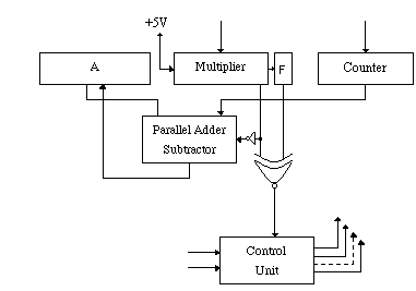
The datapath for the 8-bit code invariant calculation is given in the following figure.
The algorithm is given as follows:
The control signals have been defined as in the
following table, originally provided in Lab#3. In this
experiment, you will build a controller to implement this.
However, this time we will modify the algorithm somewhat to ease
the implementation and speed up the multiplication. The amount of
speedup will depend on the multiplier input to the circuit.
| Cycle | End | LoadI | ClearA | LoadA | Shift | ResetF |
| 0 | 0 | 1 | 1 | 0 | 0 | 1 |
| 1,3,5,7,9,11,13,15,17 | 0 | 0 | 0 | 1/0 | 0 | 0 |
| 2,4,6,8,10,12,14,16,18 | 0 | 0 | 0 | 0 | 1 | 0 |
| 19 | 1 | 0 | 0 | 0 | 0 | 0 |
The modifications are:
When we incorporate the following modifications in the design we end up with the following state diagram. (Others in this state diagram refer to all remaining not explicitly specified signals.)

The state diagram has four states. The first state is the state where the circuit waits for the Begin signal. In this state, the data at the inputs of the multiplier and counter registers will be loaded to the registers continuously, the accumulator will be cleared and the flip-flop will be reset. When the Begin signal is asserted the circuit will start to add/sub and increment (shift signal) by advancing to the state S1 or S2 depending on the input signal Mul. In state S1 the counter will be added to the accumulator, which contains the current sum. In state S2, the multiplier will be shifted to the right and the FSMCnt will be incremented (FSMCnt will be incremented during the falling-edge of the clock signal). If FSMCnt < 9 (the condition FSMCnt < 9 is equivalent to that of FSMCnt != 9, in this context) the next state will be either S1 or S2 depending on the value of the Mul; otherwise, the next state will be S3. There are some state transitions which are not shown in this current state diagram. Independent of the current state, when you assert a low Begin signal at any time, the next state must be S0. In order to be able to simplify the design procedure, you can derive your next state equations without considering the Begin signal and then connecting the Begin signal to the reset inputs of the flip-flops. This way you will need to worry about one less signal when you derive your state equations.
Note: The control unit internal counter, FSMCnt, is distinct from the datapath counter, Counter.
You are supposed to design the controller as a state-based design. The overall structure of your controller design should look like the one in the following figure:
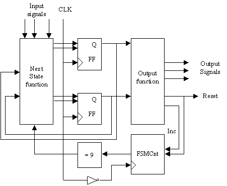
The flip-flops shown in this figure must be positive-edge triggered. Test your flip-flops before starting your design and if they are not positive-edge triggered, invert the clock before connecting the CLK inputs of the flip-flops.
In order to be able to implement the controller, you need to follow the steps given below.
In this part, you will implement the following traffic-light controller on breadboard:
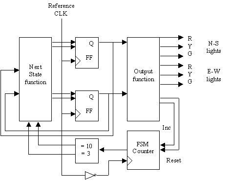
In this implementation, you are given a reference clock which generates a pulse every second. Using this reference generator as the input to your circuit, implement the traffic light controller on a breadboard. The control structure will look like the one in the first part of this experiment. The state flow should be as follows
Using the above given state flow, generate the state diagram and then implement the circuit corresponding to this state diagram on a breadboard. The overall structure of the traffic light controller should be as in the following figure:
TA Signature ________________________________________
If you do not want to spend too much time while building your circuit on breadboard, design your circuit on LogicWorks before implementing. Also while designing the circuit consider the components available in your lab kit.
Requirements:
For both parts of this experiment, please return your truth
tables, next state functions, and output functions. For the
LogicWorks part, return a printout of your implementation of the
control logic. And, of course, you should submit your design
file, following the standard "turnin" procedure.