CSE 140L Lab 1, Part 2 - UCSD Segment Display Tutorial
Spring 2007, Professor Cheng, TAs Thomas Weng, Chengmo Yang, Yi Zhu
1. Here you will design a combinational circuit that displays UCSD with the segment display. And by design, I really mean copy what you see below. But PLEASE go over it so you understand what is going on. Let's make a new project, call it Lab1Part2. Repeat the same overall steps from Part 1.
So here is a basic description of what we want to see. Digit 2 will display a U by default and Digit 1 will be totally off. This means that when no buttons are being pressed, Digit 2 will display a U. When you press down on the left button (button 1), Digit 2 will display a C. When you press down on button 2, Digit 2 will display a S. And when both are pressed down, Digit 2 will display a D. So it will look like this:

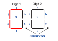
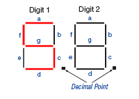

2. So by now, you should know how to build and run a basic circuit on your FPGA board. So we will assume that you know how to do that. If you do not, go back and go through Part 1 again! If you couldn't even get it to run, then come see a TA. So let's first figure out what we want to do. These are the steps you will take in general when you want to design some circuit. So let's go over what our inputs and outputs are. We in reality only have 2 inputs - push button 1 and push button 2, and we can ignore the 8 input switch. We also really only have 7 outputs to worry about, Digit Segments A to G, since we will simply turn off Digit 1 all together, as well as the two decimal points.
3. So how do we go about doing this? Let's draw a truth table! The truth table really helps specify what what we want. It is important to spend some time on specification, since everything else depends on this. So we have 2 inputs, right? That means we have 4 possible input states! We can have both buttons pressed down (0, 0), the right button pressed down (0,1), the left button pressed down (1,0) or neither button pressed at all (1,1).
4. Now, let's start with the default case, which is when neither button is pressed. This corresponds to (1,1) as our input state. When out input is (1,1), we want segments F, E, D, C, and B as 0, and the rest as 1. (Remember, setting the output to 0 turns on the red line, and setting it to high turns off the red line). So let's fill in that row on our truth table! If that does not make sense to you, look closely at the picture of U above, and notice which segments are red and which segments are not.
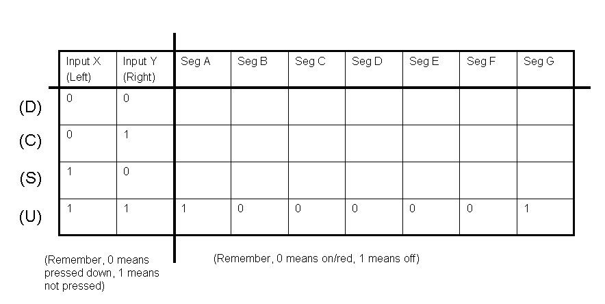
5. Are we done? No! We still need to fill in for the rest of the truth table! We finished the case where we have no buttons pushed, and want to display "U," and now need to fill in the cases where the other buttons are pressed. For the input state of (0,0) for example, which corresponds to both buttons being pressed down, you want to display a D. Therefore you write the appropriate 0s and 1s across input state (0,0). Repeat for (0,1) and (1,0). If you do not understand, come see a TA. We leave as an exercise for you to figure it out. It should take you a minute most if you know what is going on.
6. So we have a truth table! Now what? Well from this, we can develop the combinational logic required for each output! We have 7 outputs, so each of these 7 outputs needs its own combinational logic. Think of each output as only requiring the inputs (in this case we only have 2), and each of the outputs is independent of the other outputs. Yes this is kind of confusing at first, but you will get used to it. From the truth table, it becomes easy to develop the boolean logic for each output. Let's look at Segment A. Segment A is 1 only when both inputs are 1. This means that A is equal to X AND Y. This is very basic, so please make sure you understand this! Remember, we are only focusing on one output at a time! We will give you the first two outputs, A and B, so you must work out the rest. This should be very easy to do. If you are having difficulties with this, please see a TA!
A = X AND Y
B = X XOR Y
7. So now that we have our algebra, let's design our combinational circuit! Like before, let's draw out both inputs and all 16 outputs. Don't forget to set the pins appropriately!
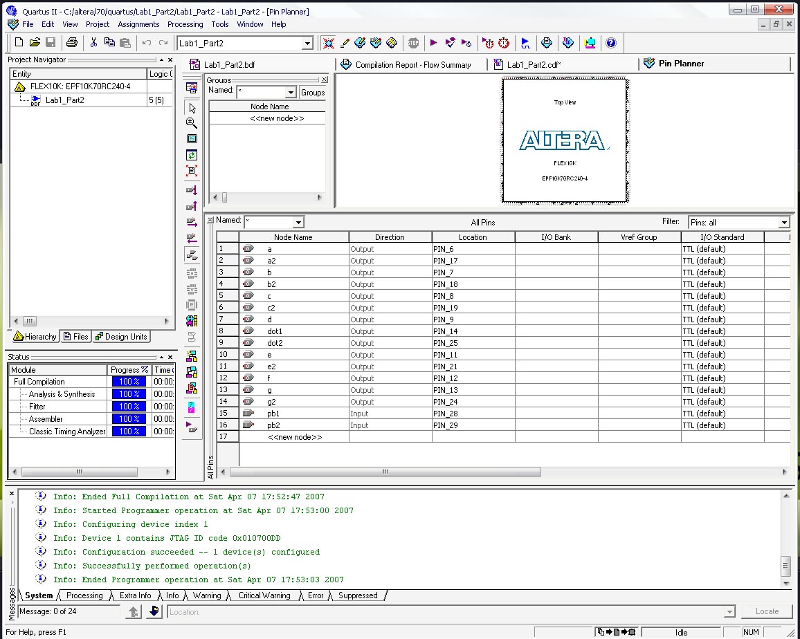
8. Since we only care about Digit 2, let's blank out the rest by connecting the other outputs to a VCC input. Complete the rest of the circuit using the AND, OR, and NOT gates. We will give you a picture of roughly what the final circuit looks like for some guidance, but by now you should already know what to do.

9. Now let's load this up on our FPGA and test it. Go through the steps to download and run the circuit on the FPGA board, similiar to Part 1. We won't bother running functional or timing simulations with this circuit, because it wouldn't really make much sense as the whole point of this circuit is to control the Segment Display.