This tutorial will walk you through the creation of a basic Finite State Machine. First, choose the FSM Editor from your project manager. Then choose the option “Use HDL Design Wizard”, and hit OK. Choose the ABEL language, and hit next. Name your file something representative of which machine you will be creating, namely, either Mealy or Moore. Next, the design wizard will ask about ports. Think of ports as inputs and outputs to your machine. Therefore, we’re going to need several input ports, one for actual input, one for the reset signal, and one for the clock signal, as well as one output port, to determine whether or not we’ve recognized our pattern. Click “New”, and proceed to enter the name of the port (you’re going to need an X, CLK, RST, and a Z), and make sure the direction is correct (whether it’s input or output, you don’t need bi-directional). After you’ve finished adding all your ports, hit next. Choose only 1 machine, and hit finish. Now that you’re all set up, it’s time to build the actual machine!
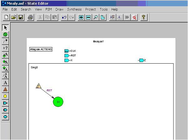
First, you’re going to need to select which type of machine to build (whether it is binary, gray, or Johnson encoded). You can do this by choosing FSM from the menu, selecting Machines, then choosing Sreg0, then adjusting accordingly from the drop down option boxes. Next, you’re going to need a start state. So, choose the S in the green circle from your toolbox on the left, and go ahead and place that start state down. Next, you’ll need to make sure you have the reset signal, so choose the orange triangle, and place it near the start state. After you click the orange triangle down onto the sheet, you’ll notice a line coming out of it. Connect this line to your start state; it’s lines like these which are responsible for transitions. After you’ve connected the line to your start state, click the “=?” button, and click the line between the reset signal and the start state. This “=?” allows us to define what the condition for transition should be, and for this particular transition, we want input from RST. If you’re confused, consult the picture on the following page.
OK, now that we’ve gotten our start state completed, we can add additional states. Add another state next to your start state. To add a transition between your two states, select the curved arrow from the toolbox on your left. Click once on the first state, then click again on the second state (the state to which you will be transitioning). After doing that, add a condition for this transition (the “=?” button). What should we put for the transition? Well, that depends on what you’re trying to do. If you want to transition when you’ve read in a 1, then put X as your condition. If you want to transition when you’ve read a 0, put !X. In my example, I chose 0, so I entered !X. I also added more transitions just for demonstration. For output, use the A attached to the curved arrow button. Select that, and then select which transition you wish to apply the output to. The format for output is Z = ^b#, where # is either 0 or 1. The Z means you’re directing this to the output port Z, and the ^b signifies a binary output, and the # will mean either true or false. An example of this is on the next page.

At this point, it would be possible to create the macro, and actually use it in your own schematics. Select Project from the menu, and choose Create Macro. After the macro has finished, return to your project manager, and start up a schematic sheet.
At this point, you should be familiar enough with the program to know what to do. Add your newly created macro to the sheet, attach a few inputs and an output probe, and try to see if your machine performs as it should. That’s the end of this tutorial, good luck with lab 3.