Lab 4 Sample Output
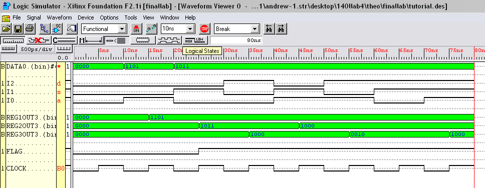
I have included some sample output so that you can make sure that your lab does what it is supposed to do. You can also see how you MUST combine your data in the simulation (flatten and use BINARY as the encoding method). Please note that if you use this specific example for the Functional Simulation of your report, you will receive 0 POINTS for that section!!!!
-
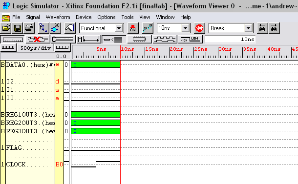
Init
- 3 bit Instruction is 000 (I2=I1=I0=0)
- 4 bit data is don’t care (can be anything, output is same)
- Register 1 input is don’t care
- Register 2 input is don’t care
- Register 3 input is don’t care
- Register 1 output (contents) becomes 0000
- Register 2 output (contents) becomes 0000
- Register 3 output (contents) becomes 0000
-
Move1
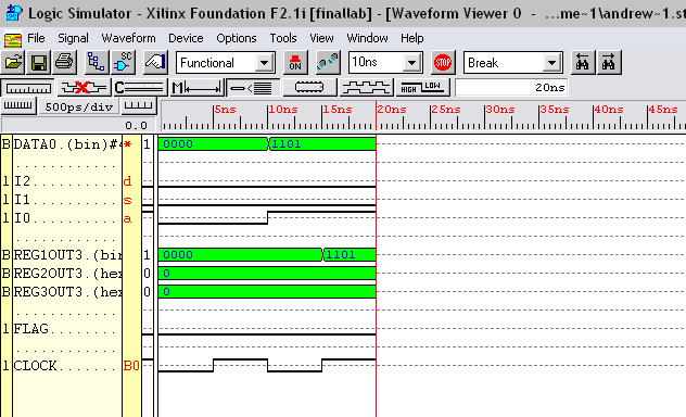
- 3 bit Instruction is 001 (I2=I1=0, I0=1)
- 4 bit data is the value to be stored in R1, in this case 1101
- Register 1 input is 4 bit data, in this case 1101
- Register 2 input is don’t care
- Register 3 input is don’t care
- Register 1 output (contents) becomes 4 bit data, in this case 1101
- Register 2 output (contents) is unchanged
- Register 3 output (contents) is unchanged
-
Move2
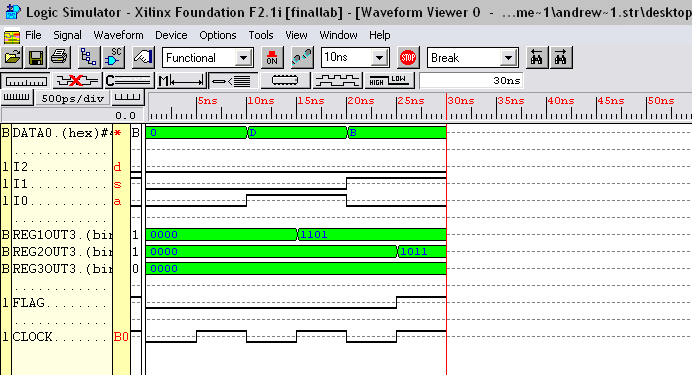
- 3 bit Instruction is 010 (I2=0, I1=1, I0=0)
- 4 bit data is the value to be stored in R2, in this case 1011
- Register 1 input is don’t care
- Register 2 input is 4 bit data, in this case 1011
- Register 3 input is don’t care
- Register 1 output (contents) is unchanged
- Register 2 output (contents) becomes 4 bit data, in this case 1011
- Register 3 output (contents) is unchanged
-
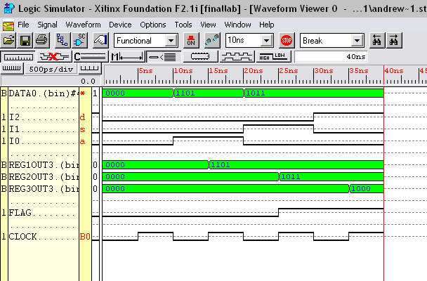
Add
- 3 bit Instruction is 100 (I2=1, I1=I0=0)
- 4 bit data is don’t care
- Register 1 input is don’t care
- Register 2 input is don’t care
- Register 3 input is the sum of Register 1 output and Register 2 output in this case, 1000 (1101+1011)
- Register 1 output (contents) is unchanged, in this case 1101
- Register 2 output (contents) is unchanged, in this case 1011
- Register 3 output (contents) becomes the sum of R1 and R2, in this case 1000
- Flag is set if an overflow has occurred, in this case true
-
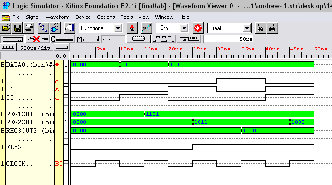
Store
- 3 bit Instruction is 011 (I2=0, I1=I0=1)
- 4 bit data is don’t care
- Register 1 input is don’t care
- Register 2 input is output from register 3, in this case 1000
- Register 3 input is don’t care
- Register 1 output (contents) is unchanged
- Register 2 output (contents) becomes register 3 output, in this case 1000
- Register 3 output (contents) is unchanged, remains 1000
-
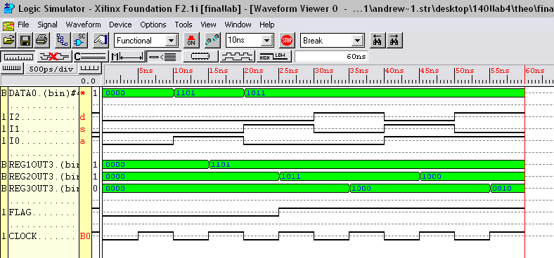
Shift
- 3 bit Instruction is 101 (I2=1, I1=0, I0=1)
- 4 bit data – first two bits are the number of bits to shift left by, last two bits are don’t cares, in this case, since the input is 1011, we will shift by 2 bits since 10 represents the number 2 in binary
- Register 1 input is don’t care
- Register 2 input is don’t care
- Register 3 input becomes the shifted output from Register 2, in this case 0010
- Register 1 output (contents) is unchanged
- Register 2 output (contents) is unchanged
- Register 3 output (contents) becomes the shifted output from Register 2, 0010
-
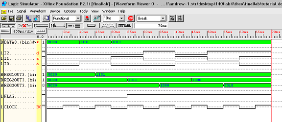
Comp
- 3 bit Instruction is 110 (I2=1, I1=1, I0=0)
- 4 bit data – don’t care
- Register 1 input is don’t care
- Register 2 input is don’t care
- Register 3 input is don't care
- Register 1 output (contents) is unchanged
- Register 2 output (contents) is unchanged
- Register 3 output (contents) is unchanged
- Flag bit is true if R1 is greater than or equal to R2. In this case, R1 (1101) is greater than R2 (1000) so the flag is set to true
-
Mask
- 3 bit Instruction is 111 (I2=1, I1=1, I0=1)
- 4 bit data – don’t care
- Register 1 input is don’t care
- Register 2 input is don’t care
- Register 3 input becomes R1 ANDed with R2, in this case 1000 (1101 AND 1000 = 1000)
- Register 1 output (contents) is unchanged, 1101
- Register 2 output (contents) is unchanged, 1000
- Register 3 output (contents) becomes R1 ANDed with R2, in this case 1000