Project Homework #1
Due: Monday, October 15, 1:00
PM
In this assignment, you are asked to implement a partitioning algorithm based
on a hybrid of the Kernighan-Lin and the Fidduccia Mattheyses algorithms. The
partitioning algorithm should be able to deal with unequal sized components; yet
since you are to implement an FM style algorithm, you do not need to implement
the KL approach of block expansion. You can simply move the components as in FM
instead. The tolerance band should be set to the maximum size of a component so
as to enable the possible movement of all components. While the net-based
implementation of FM is superior for most VLSI implementations, the edge-based
approach and the consequent gain calculations are much simpler. You should
consequently implement an algorithm that minimizes the number of cut
edges. KL for example is a cut edge minimization algorithm.
You should use the following balance criterion: floor(|V|/2 - Cmax)
<= |A| <= ceiling( |V|/2 + Cmax). The function floor
truncates the fractional part of its argument, while the function
ceiling rounds it up to the smallest integer bigger than the argument.
The number Cmax represents the size of the largest cell.
Be sure that your
initial random partition meets the balance criterion.
Algorithm:
- Initially create two random partitions.
- Calculate gains of moving each component to the other partition. (Consider
edges during this calculation).
- Choose the component with the highest gain, which satisfies the size
constraint, and move it to the other partition. Lock this component so that it
will not be considered during this iteration. Update the gains.
- Repeat moving the components from one partition to another until no more
components can be moved.
- Make all the movements up to and including the move which gives the
highest gain, permanent.
- Unlock all components and repeat until no further improvements can be
achieved.
What to turn in: Turn in a printout of your program together with the
results of your program for the circuit given in the following example. Your
program output should follow the example output in the specifications given
below. Additionally, you are required to turn-in your program via e-mail. Please do not forget to
include a
README file, which explains how to compile and run your program.
Input/Output Specification:
Here is an example
input file. In this example file, only the connections are given (no pin number
information is included). For the first project, you will not need the pin
number information available in the matrix, so you need to check only whether a
connection exist between two cells. For the subsequent projects, however, this
information will be important. The more general matrix format (which you will
use for all your projects) is as follows. The first line in the file indicates
the number of components, N, in the circuit. The following N lines
correspond to the connectivity matrix, A, of the circuit, and the last
line indicates the sizes of the components in the circuit. The non-zero entries,
Aij, in matrix A correspond to connection
between component i and j in the circuits. For the connection
between i and j, Aij indicates the pin
number of the component i, and Aji indicates the
pin number of the component j. Further assume that each connection has
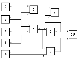
equal importance. Notice that there is a net connecting components 2, 5, and 6,
but here we'll assume that there are two edges (not three) following the
information from the matrix. The same is true for the cells 6, 7, and 8.
Whenever we have a net, this net can be modelled, as you know, with a full
graph. Yet in our projects we will consider only the edges from the net that
connect output to input pins instead. Only these edges will be given in the
connectivity matrix.
11
0 0 0 0 0 1 0 0 0 0 0
0 0 0 0 0 0 0 1 0 0 0
0 0 0 0 0 1 1 0 0 0 0
0 0 0 0 0 0 1 0 0 0 0
0 0 0 0 0 0 0 0 1 0 0
2 0 3 0 0 0 0 0 0 1 0
0 0 2 3 0 0 0 1 1 0 0
0 2 0 0 0 0 3 0 0 1 1
0 0 0 0 3 0 2 0 0 0 1
0 0 0 0 0 2 0 3 0 0 0
0 0 0 0 0 0 0 2 3 0 0
1 1 1 1 1 2 2 2 2 2 2
|
 |
Output Format:
After reading in the circuit information, your program should output the
number of components, total circuit size, the maximum component size, and the
inital partitions, and inital cutset size.
The number of components: 11
Total size of the components: 17
The maximum component size  : 2
Partition 0: 0 1 2 3 4 5 6
Partition 1: 7 8 9 10
Initial cutset size: 5
Subsequently, for each iteration, the components selected to be moved should
be displayed with the current total gain of the movements made so far.
Move  1 from Partition 0 to Partition 1.    Gain: 1
Move  4 from Partition 0 to Partition 1.    Gain: 2
Move  9 from Partition 1 to Partition 0.    Gain: 2
Move  6 from Partition 0 to Partition 1.    Gain: 2
Move  3 from Partition 0 to Partition 1.    Gain: 3
Move  7 from Partition 1 to Partition 0.    Gain: 1
Move  2 from Partition 0 to Partition 1.    Gain: 1
Move 10 from Partition 1 to Partition 0.    Gain: 1
Move  0 from Partition 0 to Partition 1.    Gain: 0
Move  5 from Partition 0 to Partition 1.    Gain: 1
Move  8 from Partition 1 to Partition 0.    Gain: 0
At the end of the each iteration, the maximum gain attained during the
iteration, the final partitions and the final cutset size should be displayed.
Max Gain: 3
Partition 0:  0 9 2 5
Partition 1:  7 8 4 10 1 6 3
Final Cutset Size: 2

Move  4 from Partition 1 to Partition0.        Gain: -1
Move  2 from Partition 0 to Partition1.        Gain: -1
Move  8 from Partition 1 to Partition0.        Gain: -2
Move  9 from Partition 0 to Partition1.        Gain: -2
Move 10 from Partition 1 to Partition0.        Gain: -2
Move  5 from Partition 0 to Partition1.        Gain: -1
Move  3 from Partition 1 to Partition0.        Gain: -2
Move  0 from Partition 0 to Partition1.        Gain: -1
Move  6 from Partition 1 to Partition0.        Gain: -1
Move  7 from Partition 1 to Partition0.        Gain: -1
Move  1 from Partition 1 to Partition0.        Gain: 0
Max Gain: 0
Partition 0:  0 9 2 5
Partition 1:  7 8 4 10 1 6 3
Final Cutset Size: 2